Počítačový svět
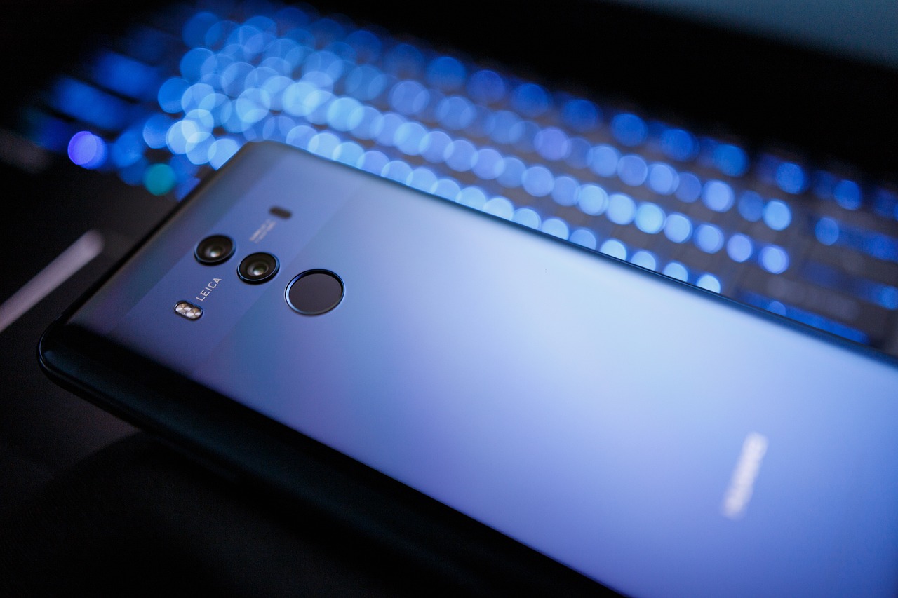
PoÄÃtaÄ je skoro můj nejlepÅ¡Ã kamarád. Abych se pÅ™iznala, tak s poÄÃtaÄem jsem se vlastnÄ› už narodila. Dokonce moje rodina...
PoÄÃtaÄ je skoro můj nejlepÅ¡Ã kamarád. Abych se pÅ™iznala, tak s poÄÃtaÄem jsem se vlastnÄ› už narodila. Dokonce moje rodina...
.jpg)
Dokončili jste stavbu domu po mnoha peripetiích a jste na něj právem hrdí? Stavba domu nebývá procházka růžovou zahradou a...
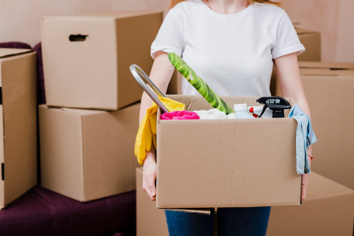
Každý, kdo někdy viděl nějaký výrobní podnik nebo dejme tomu kancelář, mi určitě potvrdí, že mají takové objekty něco společné....
Jste po náročné operaci anebo po porodu a také se vám špatně sedí? Pokud ano, tak můžete využívat také různé...
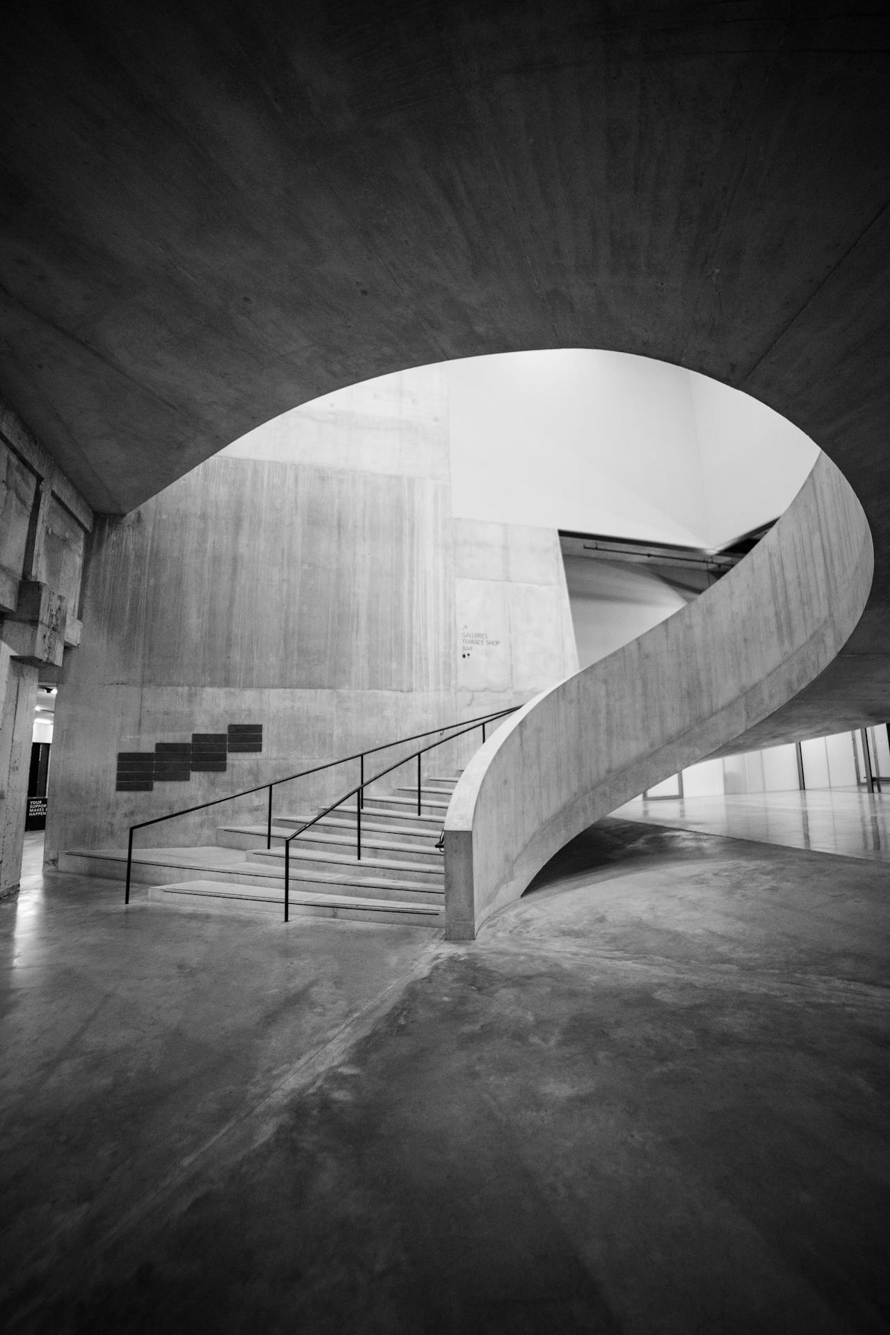
Beton je nedílnou součástí lidských životů a jejich obydlí, jen základy, domu jsou vylívané betonem a stejně tak je spousta...
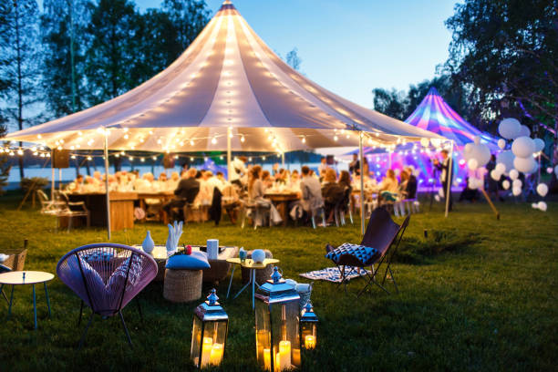
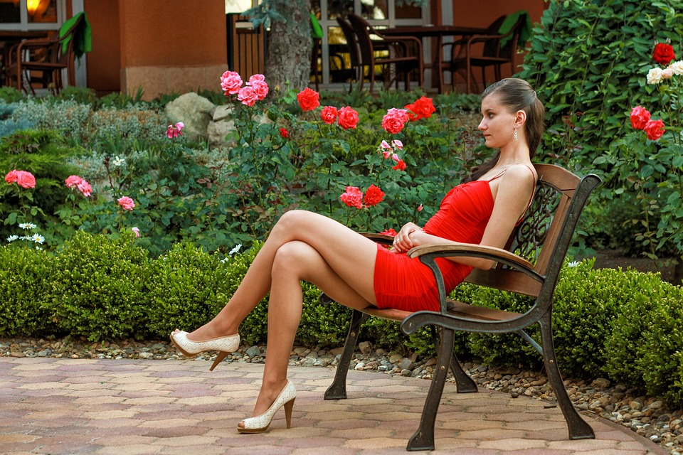
Každý z nás určitě miluje relax, protože bez relaxu se prostě neobejdeme. Vždycky potřebujeme se odreagovat. Potřebujeme jen si pořádně...
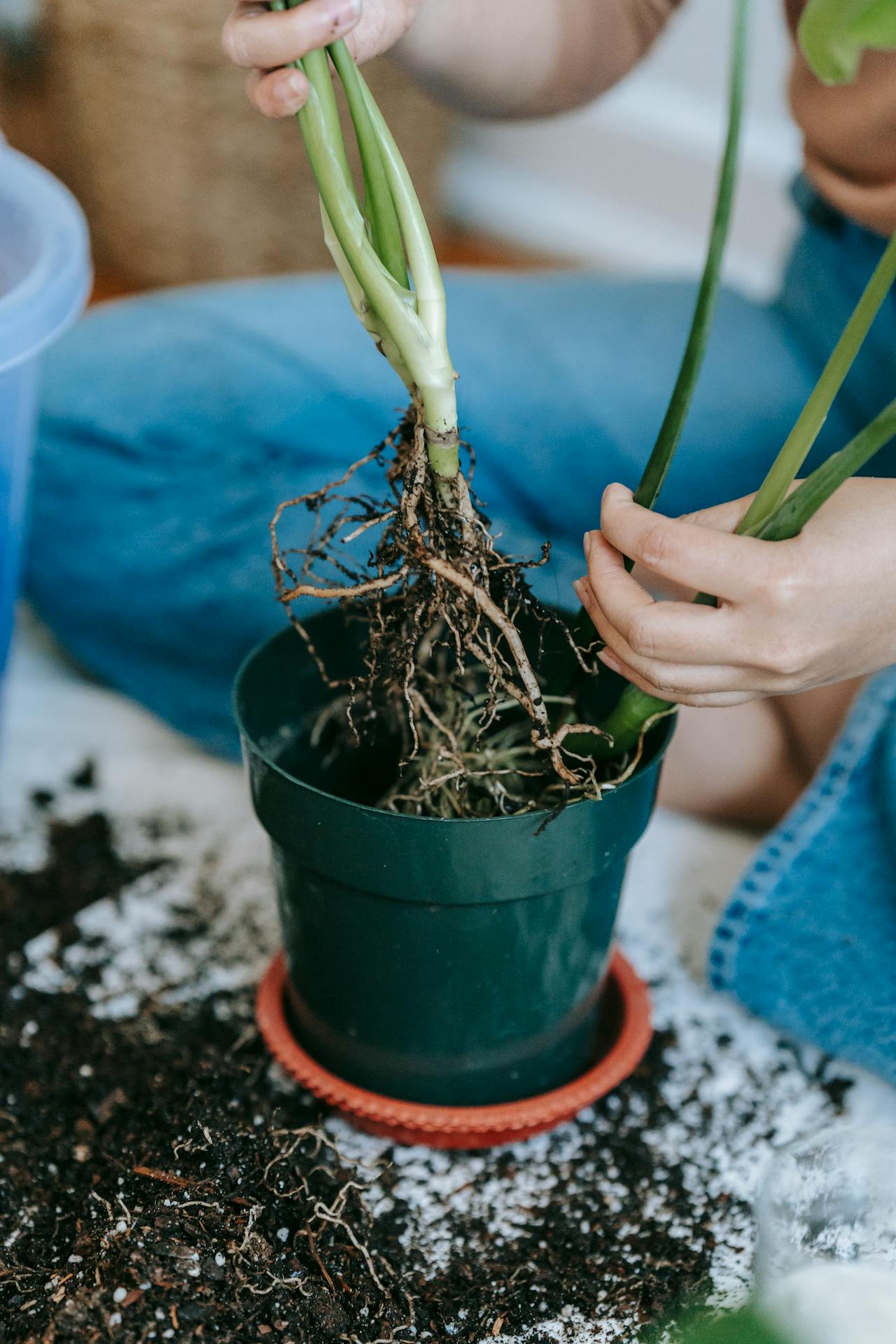
I když nemáte vhodné podmínky na za zahradničení, můžete pěstovat vlastní zeleninu. Nemusíte mít zahradu, kde byste pěstovali. Postačí vám...
_1.jpg)
Vapování je tolik oblíbené i protože mají vapeři na výběr snad nekonečně mnoho příchutí náplní do elektronické cigarety, které si...

Mnoho lidí se stydí za to, v jakém stavu mají zuby. Stav zubů je vidět i při běžném mluvení, takže...
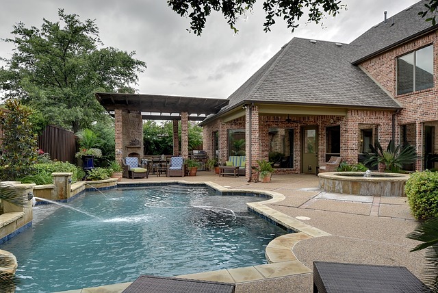
Ten, kdo již bazén má, tak musí mít problém s čištěním vody vyřešen, Jinak by se asi moc nevykoupal. Takže...